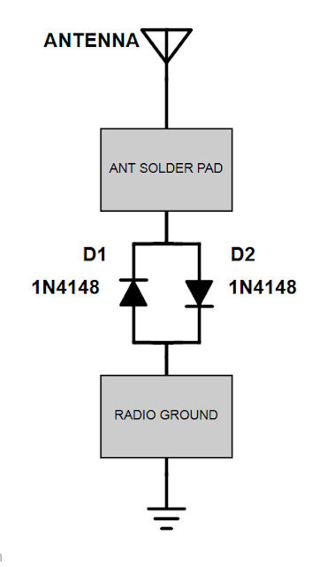
Do you want to protect your radio from static discharge while using the whip antenna? This is a must-have mod for the radio because the existing design does not incorporate static protection on the antenna input circuit. Some folks have found their radios to be "deaf" on AM and shortwave bands because a static pulse could destroy the sensitive Q1 transistor. Q1 is a 2SK152 (or 2SK291) small signal amplifier JFET. This usually occurs in low humidity conditions when a person touches the antenna to adjust it.
Theory: Installing 2 diodes in this configuration prevents high voltage spikes from passing through the antenna to the RF amplifier JFET while allowing low voltage to pass through the RF circuit.
You will need (2) 1N4148 silicon (signal) diodes or equivalent and a short jumper wire to complete this mod.
Note: This does not protect the external antenna jack so I recommend
using the same circuit between the 1/8" mono jack and your wire antenna.
"This relates to the front end burn-out phenomenon associated with the Radio Shack DX-390 multiband receiver. This happened to me with all the previously documented symptoms and I was able to repair it by replacing the input FET with a device which is available off the shelf from Radio Shack.After taking the DX-390's plastic enclosure apart by removing all the black self-tapping screws (don't forget the one down in the battery compartment) and lifting up the single p.c. board by unscrewing all the silver colored screws which hold it down, you will find Q1 near the antenna connector which in my radio was a 2SK152. Remove the dead Q1 by sucking the solder off of its p.c. pads with solder wick and measure it with the DVM to make sure it is dead--mine looked like a 31-ohm resistor from drain to source. A good FET would look like a pair of diodes with their anodes connected together at the gate. The gate is the lower terminal looking at the device from the bottom with the flat side to your right;
Paul Gili, AA1LL"
73,
JJ, W9JES

